0%

Four Circuit Protection Valves help protect separate air-brake circuits when pressure drops in one part of a vehicle’s system. Choosing the right unit is not just a matter of matching the number of ports. Its pressure range, flow capacity, connections, and mounting position must suit the vehicle and the system design. Small details matter. A fitting that appears compatible may still create installation or service problems.

A useful selection process starts with the vehicle manufacturer’s specifications and the valve’s technical data. Check operating pressures and connection sizes, then consider how the vehicle is used. Cold starts, road vibration, moisture, and frequent stop-and-go driving can all affect long-term performance. Look for clear documentation, appropriate materials, and access to replacement parts. A valve may look suitable on a workbench, yet prove awkward to inspect once installed. That deserves attention.

These four tips focus on practical checks: confirming compatibility, reviewing pressure and flow requirements, assessing construction and installation, and planning maintenance. They are intended to support informed decisions, not replace qualified inspection or manufacturer guidance. If specifications conflict or remain unclear, pause and verify them before ordering. It is easy to overlook one detail. A careful comparison can help reduce avoidable fitment issues and support dependable braking-system operation.
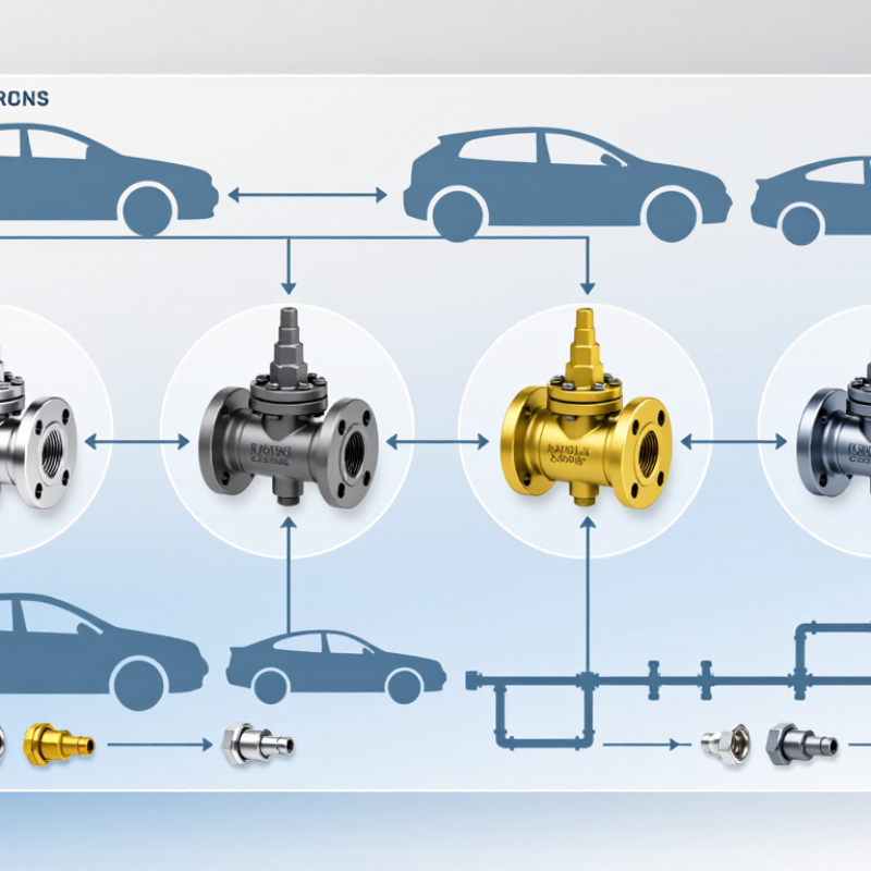
4 Tips for Choosing Four Circuit Protection Valves

Set Relief-Valve Pressure Below the Lowest Component Rating (ISO 4413)

Set the relief valve below the pressure rating of the lowest-rated component in the protected circuit. That component may be a hose, fitting, cylinder, or pressure gauge—not just the pump. ISO 4413 addresses safety requirements for hydraulic systems, including protection against excessive pressure. A valve setting should reflect those system limits, rather than the pump’s maximum capability.

Leave a margin below the component rating. Account for valve tolerance, pressure spikes, and changes caused by temperature or load. A gauge reading at low flow may not show the peak pressure near a moving actuator. Verify the setting under representative operating conditions, using suitable test equipment and the machine manufacturer’s instructions. A small gauge error matters. Record the final setting and the components used to establish the limit. It is easy to overlook a replacement hose with a lower rating; I would check the circuit again after any component change. Even a correctly adjusted valve cannot protect parts isolated from it by a closed valve or blocked line, so review the circuit layout too.

Set Relief-Valve Pressure Below the Lowest Component Rating

Illustrative example: The 140 bar relief-valve setting is below the lowest listed component rating of 160 bar. Verify actual component ratings and account for pressure spikes when designing a circuit. ISO 4413 addresses protection against pressure exceeding component limits.

Size Pressure-Reducing Valves by Outlet Setpoint and Rated Flow

Tip: Set the outlet target from the equipment’s actual operating requirement, not the valve’s maximum rating. For example, a downstream instrument needing 60 psi should be checked against the pressure it sees during both low demand and peak flow. A pressure-reducing valve may show the right setpoint at low flow, then droop as demand rises. Record inlet pressure, outlet target, fluid temperature, and the full flow range before selecting a size.

Tip: Match rated flow to the expected operating conditions. ISA/IEC 60534-2-1 defines the water-flow coefficient Cv using U.S. gallons per minute at a 1 psi pressure drop. That reference point helps compare capacity, but it is not a substitute for sizing at the actual pressure differential and fluid properties. A valve rated for 12 gpm under one condition may not deliver 12 gpm in your system. Small details matter.

Keep a margin for peak demand, but avoid choosing a much larger valve “just in case.” Oversizing can make stable outlet control harder at low flow. Check the manufacturer-neutral sizing data against the ISA/IEC calculation method, then verify the setpoint under realistic flow conditions. Real systems are messier than a worksheet; commissioning readings may reveal that the assumed demand was off.

4 Tips for Choosing Four Circuit Protection Valves - Size Pressure-Reducing Valves by Outlet Setpoint and Rated Flow

Valve type Main selection tip Key data to verify Practical check
Pressure-reducing valve Choose a valve that can hold the required downstream outlet setpoint while supplying the circuit’s expected flow. Outlet setpoint range; rated flow at the specified inlet and outlet pressures; allowable pressure drop; fluid and temperature range. Check the manufacturer’s flow data at the actual operating conditions. A valve’s port size alone does not confirm that it can deliver the required flow or maintain the setpoint.
Pressure-relief valve Set the opening pressure to protect the circuit’s lowest-rated component, and select sufficient capacity to handle the potential excess flow. Set pressure; maximum working pressure; rated relieving capacity; backpressure limits; compatible fluid. Confirm the valve can pass the required relief flow without exceeding the protected system’s allowable pressure. Keep the discharge path appropriately sized and unobstructed.
Sequence valve Select the pressure setting that allows the first operation to reach its required pressure before flow is directed to the next circuit function. Sequence pressure range; flow capacity; pressure drop; drain arrangement; downstream pressure conditions. Account for pressure losses and downstream loads when setting the valve. Verify the valve’s drain and port configuration suits the circuit design.
Unloading valve Match the unloading pressure and flow capacity to the pump and the circuit’s operating cycle. Unloading and reset pressures; pump flow; pressure rating; pilot requirements; permitted tank-line backpressure. Check that the valve unloads the full pump flow at the intended pressure and reliably returns to the loaded state when system pressure falls.

Selection note: Confirm pressure and flow ratings against the system’s actual operating conditions, fluid, temperature, and installation requirements. Use the valve manufacturer’s technical data for final sizing.

Select Sequence Valves by Pilot Pressure and Actuation Order

4 Tips for Choosing Four Circuit Protection Valves

Select Sequence Valves by Pilot Pressure and Actuation Order

A sequence valve helps one hydraulic function occur before another. For example, a clamp cylinder can secure a workpiece before a second cylinder advances. Choose the valve’s pressure setting from the real load requirement, not a guessed catalog value. Include pressure losses through hoses, fittings, and filters. Measure it hot.

Check how the valve receives its pilot signal. An internal pilot senses pressure at the inlet, while an external pilot can respond to pressure from another part of the circuit. Confirm the design and drain arrangement in the valve documentation. Pilot pressure must be high enough to shift the valve, but the setting must remain within the limits of every connected component.

Map the intended actuation order and identify what happens if the first actuator stalls. A stalled cylinder may raise pressure and trigger the sequence valve earlier than expected. That detail is easy to miss. Review the circuit schematic, then test the order under realistic loads and flow rates. Small margin matters: leave enough pressure separation for reliable sequencing without forcing the system to run unnecessarily close to its pressure limit.

Rate Counterbalance Valves for Load Pressure, Flow, and Pilot Ratio

Tip 1: Measure the actual load pressure, including changes as the actuator moves. Set the counterbalance valve according to the valve maker’s instructions and the circuit’s maximum pressure rating. A setting too close to normal load pressure can cause drift; an excessive setting may create heat and sluggish motion. Leave room for real operating variation.

Tip 2: Match the rated flow to peak actuator flow, not just average pump output. Check both pressure drop and oil temperature at expected flow. A valve that is too small can restrict movement and waste energy. Watch the return path, too.

Tip 3: Choose the pilot ratio for the control behavior your circuit needs. A higher ratio can reduce the pilot pressure needed to open the valve, but it may make operation more sensitive to pressure changes. A lower ratio may offer steadier control while requiring more pilot pressure. Verify the choice with circuit calculations.

Tip 4: Test under load. Slowly raise and lower the actuator, then inspect for drift, chatter, and temperature rise. Record the pressure readings. Field results may challenge the neat calculations, so revisit the setting if motion feels unstable.

FAQS

How should I set a hydraulic relief valve?

Set it below the pressure rating of the lowest-rated protected component. That may be a hose, fitting, cylinder, or gauge. Leave a safety margin for pressure spikes and valve tolerance.

Why shouldn’t I use the pump’s maximum pressure as the limit?

The pump may tolerate more pressure than a connected hose or cylinder. The weakest component sets the circuit limit. Check every rating.

How can I verify the relief-valve setting?

Test under representative loads and flow conditions with suitable equipment. A low-flow gauge reading may miss a pressure spike near a moving actuator. Record the final setting.

What should I check after replacing a hydraulic component?

Confirm the new component’s pressure rating and review the circuit setting. A replacement hose can have a lower rating. I would recheck the whole circuit, too.

How do I choose a sequence valve setting?

Base it on the real load and include pressure losses through hoses, fittings, and filters. Measure it hot. Small margins matter.

What is the difference between internal and external pilot signals?

An internal pilot senses pressure at the valve inlet. An external pilot receives a signal from another circuit location. Check the valve’s pilot and drain requirements.

What can cause a sequence valve to shift earlier than expected?

A stalled cylinder can raise pressure and trigger the valve. Test the intended actuator order with realistic loads and flow rates. That detail is easy to miss.

How do I size and test a counterbalance valve?

Match its rated flow to peak actuator flow, not average pump output. Test raising and lowering under load, then check for drift, chatter, and heat. Revisit the setting if motion feels unstable.

Conclusion

Choosing Four Circuit Protection Valves requires matching each valve to the system’s pressure, flow, and operating sequence. Set the relief valve below the pressure rating of the system’s lowest-rated component, following the safety principle in ISO 4413. For a pressure-reducing valve, consider both the required outlet pressure and the flow it must handle so that downstream equipment receives stable, suitable pressure.

Sequence valves should be selected according to their pilot-pressure requirements and the order in which actuators must operate. Counterbalance valves need to be rated for the load pressure and flow, with a pilot ratio suited to the application. Reviewing these factors together helps protect components, support predictable operation, and ensure that each circuit responds appropriately under changing loads.

Elowen

Elowen

Elowen is a dedicated marketing professional with a strong understanding of the company’s products, customers, and industry landscape. Through a combination of strategic insight, clear communication, and practical market knowledge, Elowen helps translate complex product features into useful......